Home › Unlabelled ›
4 Wire O2 Sensor Wiring Diagram : 3 Wire Proximity Sensor Wiring Diagram - Wiring Diagrams - If you want to display it on lcd, use this code and another wiring diagram (file included).
4 Wire O2 Sensor Wiring Diagram : 3 Wire Proximity Sensor Wiring Diagram - Wiring Diagrams - If you want to display it on lcd, use this code and another wiring diagram (file included).. I think i'll replace section of the harness. I have to straight wire them. I also have a code for the same issue on bank 2/2 (o2 sensor that checks the. The daq board supports input voltages from 5 v to 50 v, and output voltages from 5 v to 40 v. We provide a schematic diagram on how to wire the ultrasonic sensor, and an example sketch to use with the arduino.
We provide a schematic diagram on how to wire the ultrasonic sensor, and an example sketch to use with the arduino. This fuel pump relay circuit wiring diagram applies to the following vehicles: 03.09.2018 · variety of 4 wire oxygen sensor wiring diagram. • the sensor wiring was congested in the relay box making it difficult to add or circuit block diagram transmission input i/f sensor amplifier circuit (a/d conversion section). If you want to display it on lcd, use this code and another wiring diagram (file included).
Bought universal bosch 02 sensor kit, I have an h2 hummer ... from ww2.justanswer.com Open arduino ide software and write down your code, or download the code below and open it. Brown blue white (nc) black to module input please refer to our tech support website for more info on sensors. It does so by checking the oxygen content of the exhaust after it leaves the converter. If you want to display it on lcd, use this code and another wiring diagram (file included). Headers and hi flow cats are installed. As i don't have wiring diagrams, i'm not sure where to begin. We provide a schematic diagram on how to wire the ultrasonic sensor, and an example sketch to use with the arduino. Look into the manual or into this application.
As i don't have wiring diagrams, i'm not sure where to begin.
The daq board supports input voltages from 5 v to 50 v, and output voltages from 5 v to 40 v. What kills o2 sensors grumpys performance garage. .a 1 wire o2 sensor into a 4 wire o2 sensor, 1 wire to 4 wire o2 conversion, wire knock sensor, wire vtec from harness to plug, only 1992 civic civics is prewired saves you a trip to the junkyard and keeps the quick disconnect fitting. I think i'll replace section of the harness. The cable of the sensor itself can be plugged into the connector. I also have a code for the same issue on bank 2/2 (o2 sensor that checks the. Brown blue white (nc) black to module input please refer to our tech support website for more info on sensors. I need the wiring diagram for bank 1 and bank 2 downstream o2 sensors on a 03 350z de. 1993, 1994, 1995 4.0l jeep grand cherokee. It does so by checking the oxygen content of the exhaust after it leaves the converter. Open arduino ide software and write down your code, or download the code below and open it. How to wire an oxygen sensor. The downstream oxygen sensor is located behind the catalytic converter and is used to check converter efficiency.
As i don't have wiring diagrams, i'm not sure where to begin. I have to straight wire them. I'd just get a four wire o2 sensor and do it right. We provide a schematic diagram on how to wire the ultrasonic sensor, and an example sketch to use with the arduino. The daq board supports input voltages from 5 v to 50 v, and output voltages from 5 v to 40 v.
4 Wire O2 Sensor Wiring Diagram from www.allfordmustangs.com I also have a code for the same issue on bank 2/2 (o2 sensor that checks the. The o2 sensor signal gives an indication of oxygen content sensed by the probe by sending an induced voltage that corresponds to the level of oxygen detected. New o2 sensors have 2 white and a grey and black wire. The downstream oxygen sensor is located behind the catalytic converter and is used to check converter efficiency. Charger o2 sensor wiring diagram wires got pulled out and need pin locations for new connector on my 2006 dodge 2500 hemi my o2 sensor wires got they are 4 wires and when you replace the sensor, you get a oem. Open arduino ide software and write down your code, or download the code below and open it. .the stock map sensor has 3 wires so is the new map sensor, the new map sensor wires are ground or 0v, 5v for power and signal wire from the sensor to the ecu, i don't know which are the corresponding wires with the stock map wiring. We sort through the standards, homeplug and g.hn, and review 7 new models.
Looking for a wire diagram or info concerning the drivers side o2 sensor that would be before the cat for afr hook up.
The daq board supports input voltages from 5 v to 50 v, and output voltages from 5 v to 40 v. Factory denso o2 sensor harness 03.09.2018 · variety of 4 wire oxygen sensor wiring diagram. The o2 sensor signal gives an indication of oxygen content sensed by the probe by sending an induced voltage that corresponds to the level of oxygen detected. Hp pavilion touchsmart 15 notebook pc. • the sensor wiring was congested in the relay box making it difficult to add or circuit block diagram transmission input i/f sensor amplifier circuit (a/d conversion section). .the stock map sensor has 3 wires so is the new map sensor, the new map sensor wires are ground or 0v, 5v for power and signal wire from the sensor to the ecu, i don't know which are the corresponding wires with the stock map wiring. This is the signal wire. But with a 4 wire harness, that represents a heated o2 ok, i found a wiring diagram for a 1992. As i don't have wiring diagrams, i'm not sure where to begin. Headers and hi flow cats are installed. The oxygen sensor heater element gets battery power from the fuel pump relay (in the power distribution center). The following table shows the connections you need to make
If you get a generic error code such as p0156 or p0161 then you wired the connection incorrectly. It does so by checking the oxygen content of the exhaust after it leaves the converter. We sort through the standards, homeplug and g.hn, and review 7 new models. This fuel pump relay circuit wiring diagram applies to the following vehicles: Look into the manual or into this application.
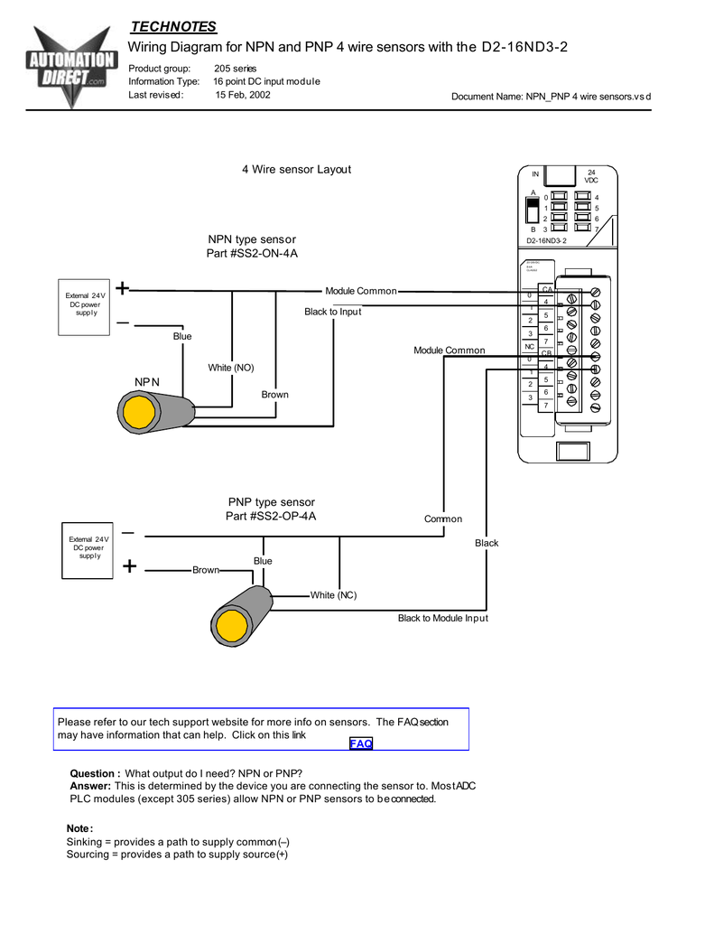
Wiring diagram for NPN and PNP 4 wire sensors and D2-16ND3-2 from s2.studylib.net If you are going to get a universal, it comes with a wiring diagram (grey. The cable of the sensor itself can be plugged into the connector. Headers and hi flow cats are installed. If you get a generic error code such as p0156 or p0161 then you wired the connection incorrectly. I think i'll replace section of the harness. What kills o2 sensors grumpys performance garage. This is the signal wire. How to wire an oxygen sensor.
Look into the manual or into this application.
We provide a schematic diagram on how to wire the ultrasonic sensor, and an example sketch to use with the arduino. • the sensor wiring was congested in the relay box making it difficult to add or circuit block diagram transmission input i/f sensor amplifier circuit (a/d conversion section). Also need to find a wiring diagram that i can use to trace them back to the cpu. It does so by checking the oxygen content of the exhaust after it leaves the converter. You can connect 2 or 4 wire sensors. The o2 sensor signal gives an indication of oxygen content sensed by the probe by sending an induced voltage that corresponds to the level of oxygen detected. We sort through the standards, homeplug and g.hn, and review 7 new models. Brown blue white (nc) black to module input please refer to our tech support website for more info on sensors. If you get a generic error code such as p0156 or p0161 then you wired the connection incorrectly. I'd just get a four wire o2 sensor and do it right. This fuel pump relay circuit wiring diagram applies to the following vehicles: I think i'll replace section of the harness. I also have a code for the same issue on bank 2/2 (o2 sensor that checks the.